
Walser Pistenraupen Modellbau
The front equipment carrier can be greatly upgraded with hydraulic hoses.
The printed parts are available in the Thangs/Shapeways Webshop of AT modellbau.
For the hydraulic connectors original brass printed parts were available at the Shapeways Shop from AT modellbau. In addition, silicone strands in two diameters (available from Conrad 1.9 mm outside and 2.3 mm outside) and brass tubes (2.5 mm outside / 2.0 mm inside and 2.0 mm outside / 1.5 mm inside) are required . Brass tubes are available from Fechtner Modellbau, for example, but the 2.5 mm tubes have to be drilled out.
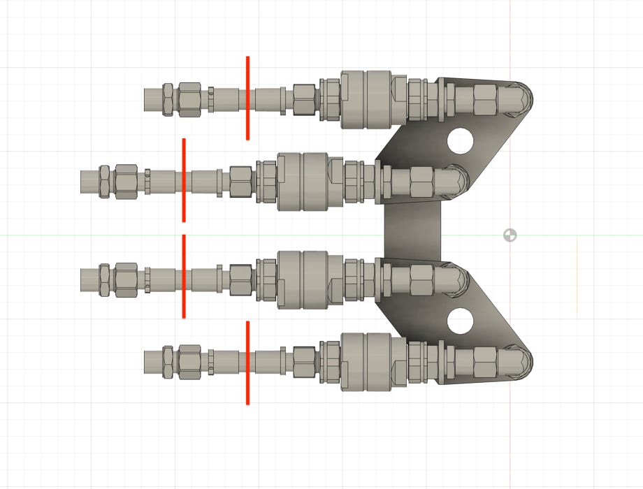
In order to keep the costs for the printed part low, all required connectors for the front device carrier and the blade are combined to form one printed part. These must be separated accordingly using the red lines in the picture below. A cutting disc on a Proxxon or Dremel is best suited for this. The parts colored red are not needed.
The abbreviations mean:
H-W: lifting cylinder, chassis side
H-Z: lifting cylinder, on the cylinder
N-W: blade angle cylinder, chassis side
N-Z: blade angle cylinder, on cylinder
S-W: Swivel cylinder, chassis side
S-Z: Swivel cylinder, on the cylinder
Ta-V: Tilt cylinder outside, on the hydraulic distributor
Ta-Z: Tilt cylinder outside, on the cylinder (only on the right tilt cylinder)
Ti: Tilt cylinder inside. These ere connected crosswise, with the curved connectors at the top
HydV-W: to the hydraulic distributor on the quick-change system, on the chassis side
HydV-V: to the hydraulic distributor on the quick-change system, distributor side
VS: Closure stopper if a hole on the tub side is not required
Short brass sleeves are soldered onto the connectors. The sleeve always comes to the end where small ridges can be seen at the bottom. This is a red plastic clamp on the original. See image below. If you want to make the sleeves true to the original, then the 2 mm sleeves are 2.4 mm long and the 2.5 mm sleeves are 2.7 mm long. I made them with 3.0mm and 3.5mm so I have a little more soldering and gluing area. I glued the stripped part of the silicone strand with Pattex Extrem.
Since some of the connections look quite similar, I sorted them accordingly. To paint them silver, I skewered them onto round toothpicks:
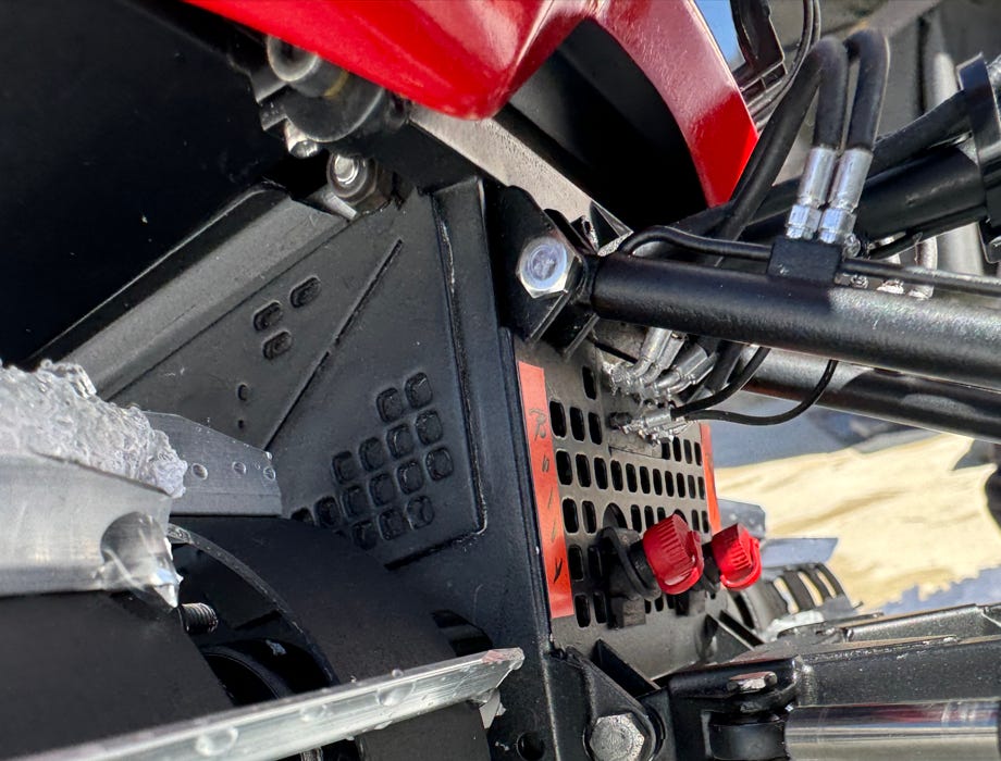
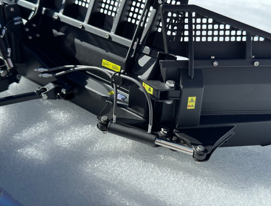
With the newer versions of the equipment carrier, only 3 thick hoses go from the chassis to the hydraulic distributor. If you have the 8-way equipment carrier from Pistenking, two of them are already the cable pulls to the tilt cylinders. In the original, the 3 hoses are mounted on the left side of the hydraulic distributor. Since the Pistenking equipment carrier with the tilt function cannot be true to the original in this area and also does not have the newer, block-shaped cover, I simply guided the third hose into the middle of the hydraulic distributor (see large cover photo above).
For the connection to the chassis, I cut out part of the front grille and glued in a block with eight 2.0 mm holes. The hydraulic connectors on the chassis side are glued into these. This isn't exactly true to the original either, but as with the hydraulic distributor, a compromise has to be made here because of the tilt function. I can live with that because this area isn't really visible anyway.
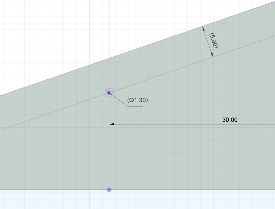
The quick-change connectors to the blade side cylinders were available in the AT-modellbau Shapeways shop as a true-to-original brass printed part. At the front are the connectors to the side cylinder, which have to be separated along the red lines. The part is also to be cut in the middle. To ensure that the blade remains removable, these parts are each attached to the quick-change frame with an M1.6 screw. The exact position for the hole can be seen in the drawing below, the 30 mm is from the outer edge of the middle tower, the 5 mm from the top edge.
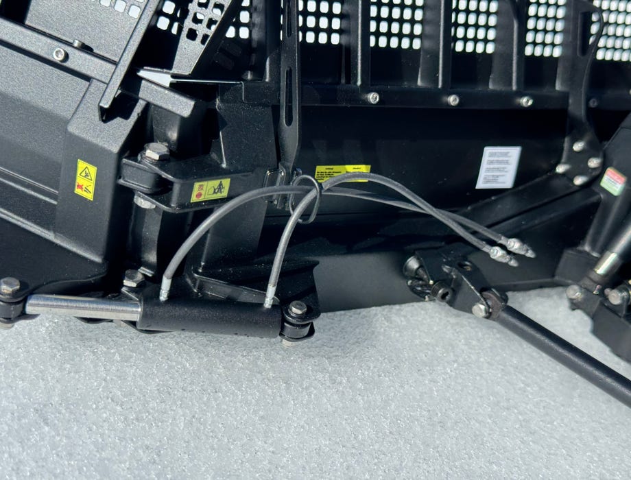
Only one hose leads to each swivel cylinder. On the chassis side, a small block needs to be inserted below the main block, where the 90-degree connectors point downwards. A 1.5 mm hole must be made on the inside of the piston rods directly after the ball heads, where the connectors are glued in.
I haven't implemented this yet, the picture from the original can serve as instructions (photographer unknown):

Diese Seite verwendet Cookies. Sie stimmen der Verwendung von Cookies durch Anklicken von “OK” zu. Nähere Informationen finden Sie in unseren Datenschutzbestimmungen.
This page is using Cookies. You are permitting the use of cookies by clicking on “OK”. More information can be found at our Privacy Protection.


